Here is more of what has gone on getting it right, for all who may be interested.
 The ratings of negative ion generator components (a.k.a. air charger units), as given by vendors, are often very confusing. One can find these parts of apparently identical model, sold by different vendors, publicly rated at 10 million particles per cubic meter, 30 million per cubic centimeter, 40M pcs/cm3, and even 1.9 trillion per cm3.
 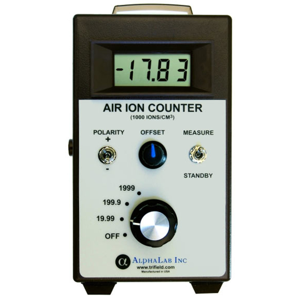 I (Jonathan) saw quite a lot of inconsistent results in the first big iteration of this project
 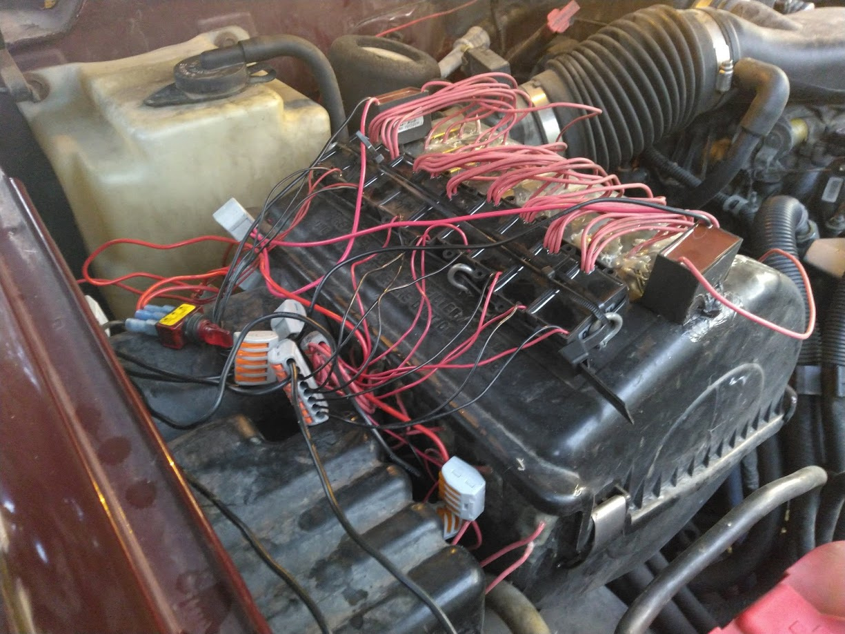 (see left, a total of 14!). So I decided that, if we were going to do well with this, we really needed to get rigorous with numbers, and find out what the actual output of these electronics packages are, before mounting them again or giving them to friends. I wasn’t sure I could justify the cost of the meter – $500 – but a silent partner offered, and so we have one now, and here is the current state of our knowledge. It’s important to know that the meter results are imprecise, the precision is reportedly +/- 25%, though the visible variability over time is a lot less. Where I report “10”, I’ll study numbers for a half-minute or so, and wait for it settle down.
The first thing I did was test several of of the electronics packages I had. Some were altogether bad, zero output or close; the others, though, produced quite surprising results when tested in various ways.
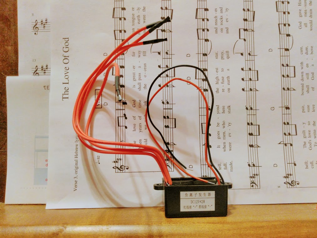
All of the ones I had then, are of a common type, one of which is pictured at left. There are two thin wires for 12VDC input — they have worked just fine with the ~15VDC one finds in an auto electrical system — and four thicker wires for negative ion emission, at the ends of which are small carbon-fiber brushes. I have found a wide range of vendors of these, all rated from 24 million particles to 40 million, generally per cm3, and most also including a standard testing distance of 10cm. When I started working with this model, they were new to the market, and were the most powerful components I could find, all others said to be topping at 10 M/cm3. Anyhow, very recently I tested carefully, used a distance of 10cm, and found the following:
| Just one of the four carbon fiber brushes near the meter input, 10cm away. I tested all four of the brushes the same way, and all four of them were producing this same level. | 10 M/cm3 | 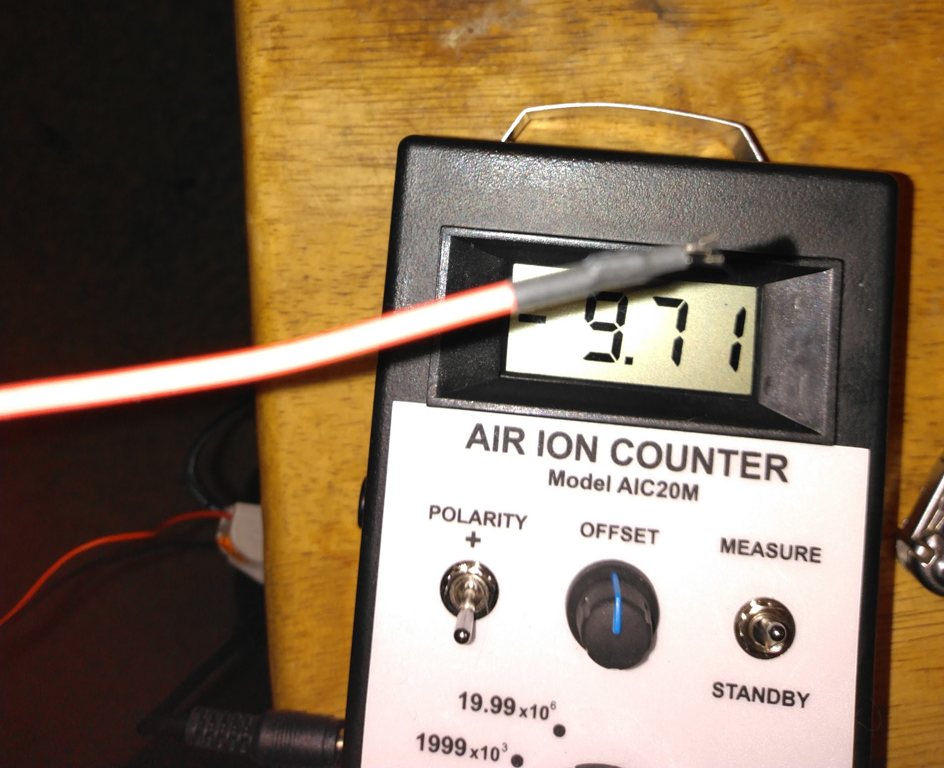 |
| All four carbon fiber brushes active and together. 10cm away. | Still 10 M/cm3, but probably a bit more than the first. Nowhere near four times, nothing close to what was expected | 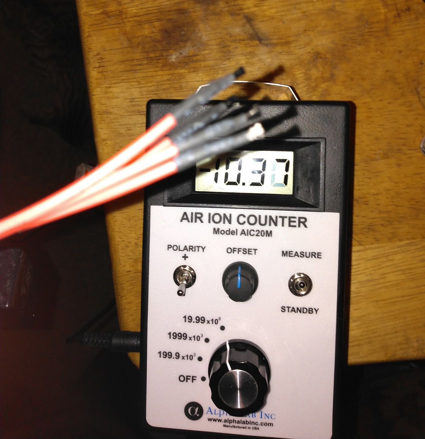 |
| All four carbon fiber brushes active and together, but electrically connected. 10cm away. | Still effectively 10 M/cm3. Probably a bit more yet. Again, clearly, nowhere near four times. | 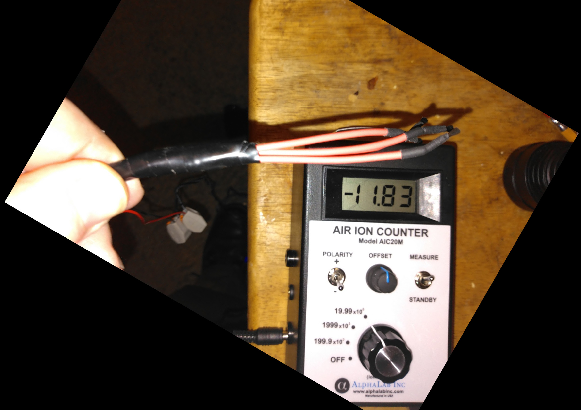 |
So the question is, what does the above mean? Well, for starters, it means that each output does put out 10, so the 40 is honest mathematically, at least for all the working units I’ve tested so far. But it also means that something really odd happens when multiple outputs are in proximity, and also when multiple outputs are wired together. I have no idea what this is, but the facts have to factor into our design, and quite significantly. In the first iteration of this project I had 12 identical electronics packages of the above (quad-output) sort installed, and two more of a later design, with all of the brushes inside the air filter compartment, 36 of them within about an inch of each other. That iteration ceased when I discovered that some of the brushes were not physically stable as I had thought they were, there was rubbing and other errata, so some months of observations could not be depended upon. But given the measurements above, we have one major conclusion:
- Multiple identical brush-to-air outputs in a small area, and multiple brush-to-air outputs pre-connected electrically, do not add together their output. The numbers may add slightly, but not significantly.
Towards the end of the first iteration, when I was noticing returns not matching, I had a thought. I was throwing the engine intake air across the little carbon-fiber brushes, which is how the units are used in air conditioners and the like, 40 little brushes in all. What if I added one more unusual element: what if took one quad unit, cut off those carbon-fiber brushes, bound them all into one alligator clip, and clipped it to the metal mesh holding this vehicle’s air filter together?
And so I did it, and here is what it looked like. 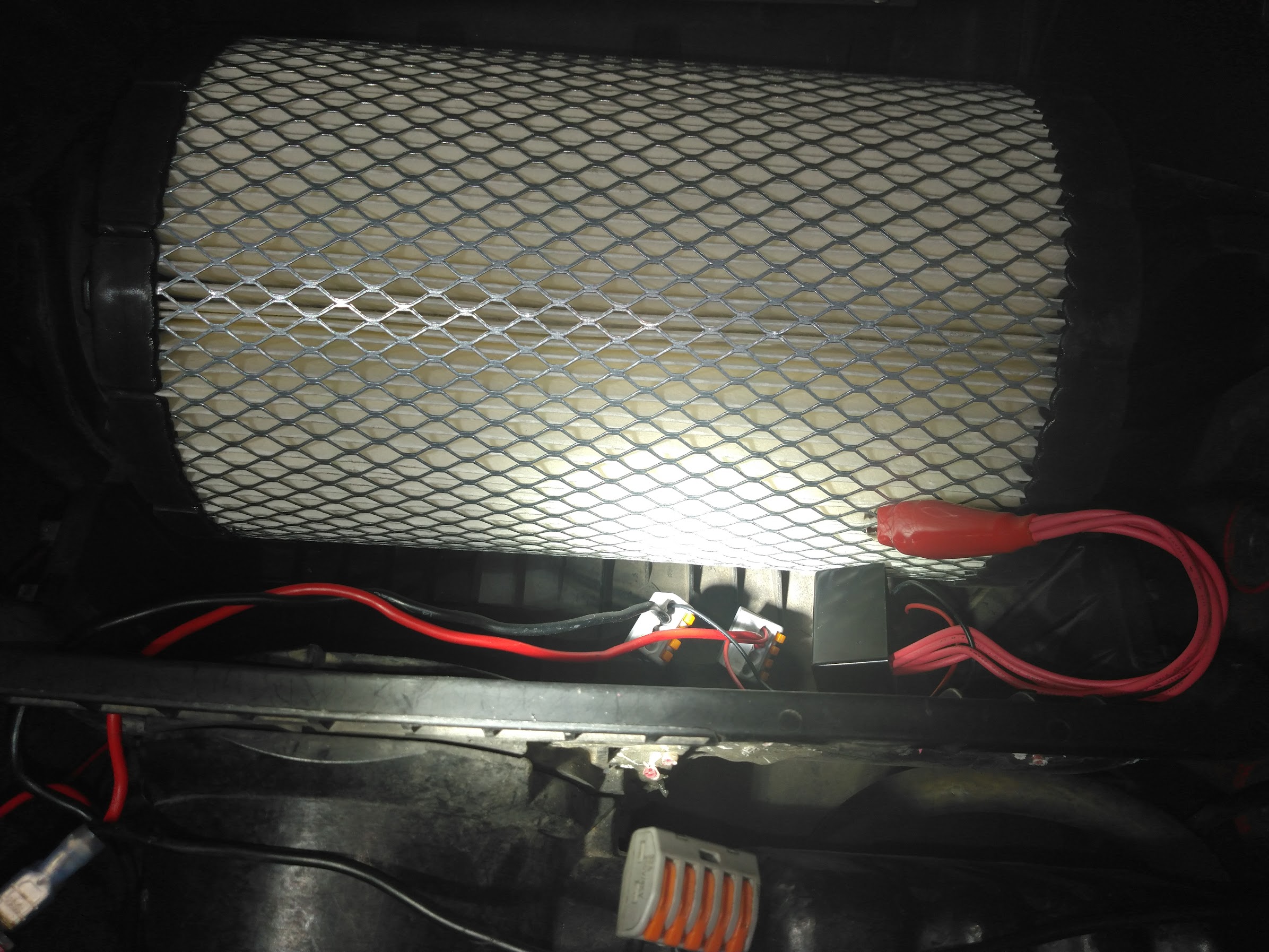
The response of the engine was astonishing: it howled, and immediately. Sweet Lori and I had never heard an engine howl before. I immediately shut engine off, disconnected the 14 brushes-in-air units, and tried again with just the clip. That ran OK, but I had already done a bit of harm. We learned a major lesson over the next six months:
- The way to tell when you’re sending too much ionized air in for the temperature, is one or more spark plugs will foul.
In this case, the engine had 220,000+ miles on it, and two of the cylinders are slightly low in compression (so says my excellent mechanic), and it’s these whose plugs tend to foul. It took a while and a few repetitions before it dawned on me that the above is what was happening; some lessons come a bit more difficult than others ☺
 So after learning the above, while Matt graciously and patiently replaced plugs a few times, I tried a number of things, and eventually found that the above-pictured clip did a great job…down to 32 F (0 C). The morning came that it dipped below 32, and one spark plug fouled again. After my mechanic got that fixed for me again (he is very patient), I kept all of this disconnected for some time, and thought about things.
 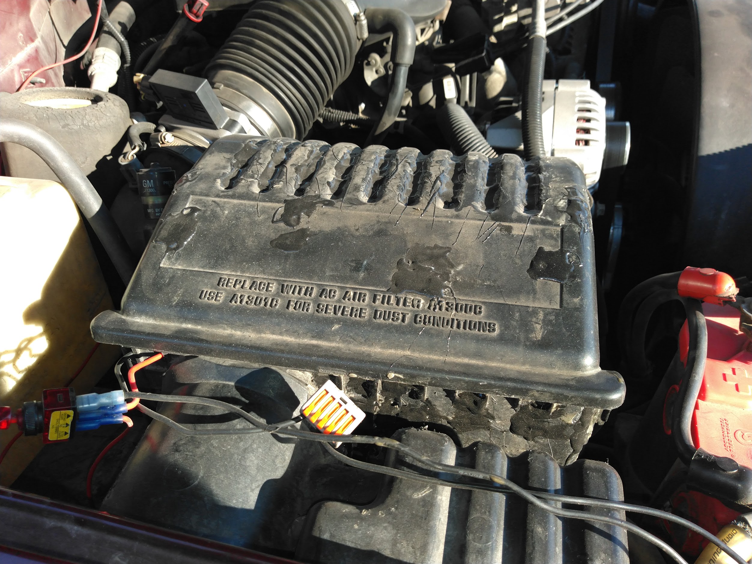 I permanently removed the original fourteen (and filled the holes with plastic-bonding epoxy), because obviously the one clip produced much more output. And after I had the meter and had tested the standard quad-output ionizer units I still had, I installed one in simple fashion,
  with carbon-fiber brushes in moving air, to help get through the winter while better was thought out. It was attached to the air filter compartment wall using 3M Dual Lock, which is something like Velcro, but stronger and both sides are the same.
And that continued to help. So brushes-in-air is not an option to be completely thrown out. But shortly I tried using a single-output air charger unit, with a voltage regulator which takes in anything the electrical system gives, and puts out a very steady 5.0VDC. This stabilized things amazingly, with excellent results…until the ambient air temperature went to freezing! After a lot of experiences, the lowest safe point appears to be about 35F (1.67C). My current theory is that tiny frozen ice particles in the air may do something very unexpected in the unusual conditions. What, exactly, I’m not sure. I have wired in a thermostatic switch which senses the temperature inside the air filter compartment, and keeps this whole system off until it senses higher than 1.67C; this seems to be a very satisfactory solution.
I have also ordered and received four different kinds of air charger units, from four different sources, for testing. All of them are single-output. Thus far all of them have measured at 10 M/cm3 ion output, except one boxy type using metal pins, where you could see the corona, you could smell the ozone (!), but the meter showed it was putting off less than half of 1 M/cm3. All of this was quite a bit of a surprise, given the advertising of them. It means that there is effectively one kind of unit out there, at least found so far, and the quad units are just four of them in a package. Much more recently I have been seeing single-brush units advertised as putting out 20 M/cm3, so perhaps an additional option exists. Haven’t verified that with a meter yet.