Here’s a rundown on assembly, with notes on simplifying sans clip:
- Fuse tap plugged into the engine compartment fuse box. Choose a fuse for a circuit powered when the ignition switch is on, pull that fuse out, plug in the fuse tap, plug the fuse and a second identical fuse into the fuse tap. Now you have a red wire to extend into anything you want, including charging that air :-) Do secure it well, until you are ready to use it.
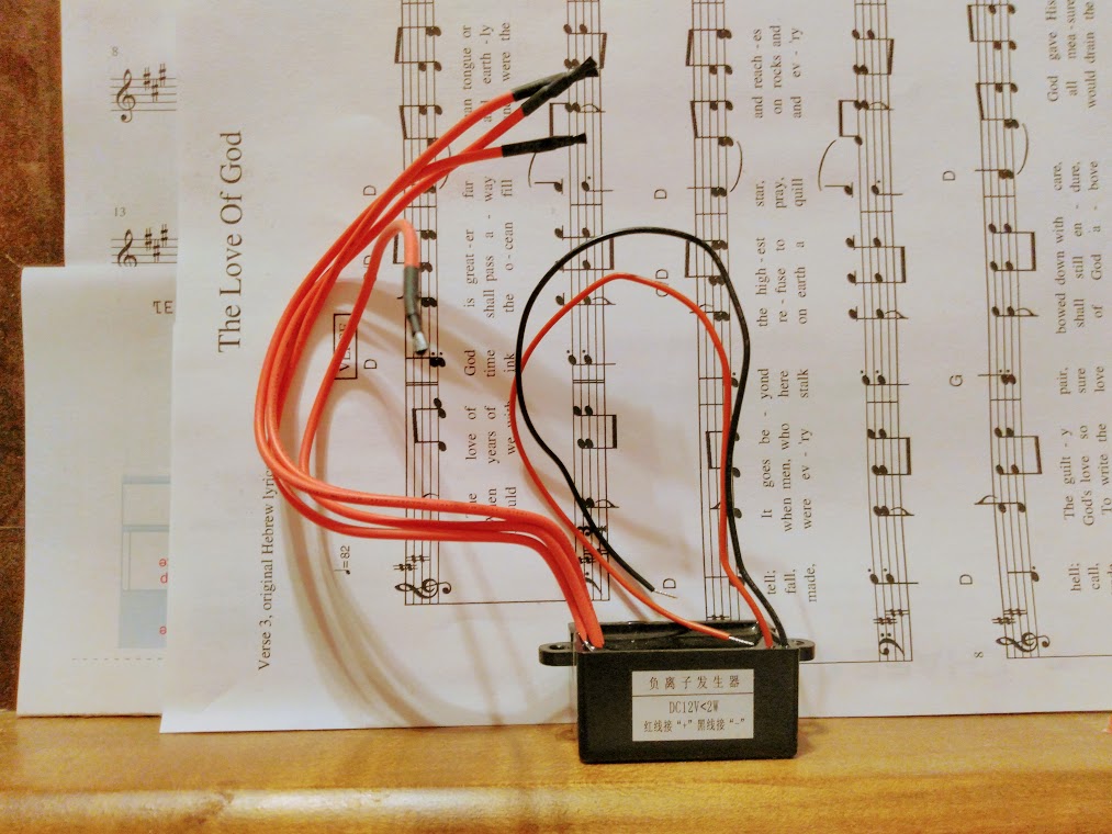 To get a feel for what’s going on, I’ll suggest you set up your first build to charge air directly. I’ll suggest using one, two, or three of these (see pic to the right). You can buy them here, quite inexpensively at this writing. Be sure you get the 12VDC version, the others won’t work in a car. We can supply you with some which we have tested for output, too. Just wire them to the fuse tap for power, either battery-negative or body for ground, stick the little carbon-fiber brushes into holes drilled into the air-filter compartment, and glue them in with plastic-bonding epoxy one can find at an auto-parts store.

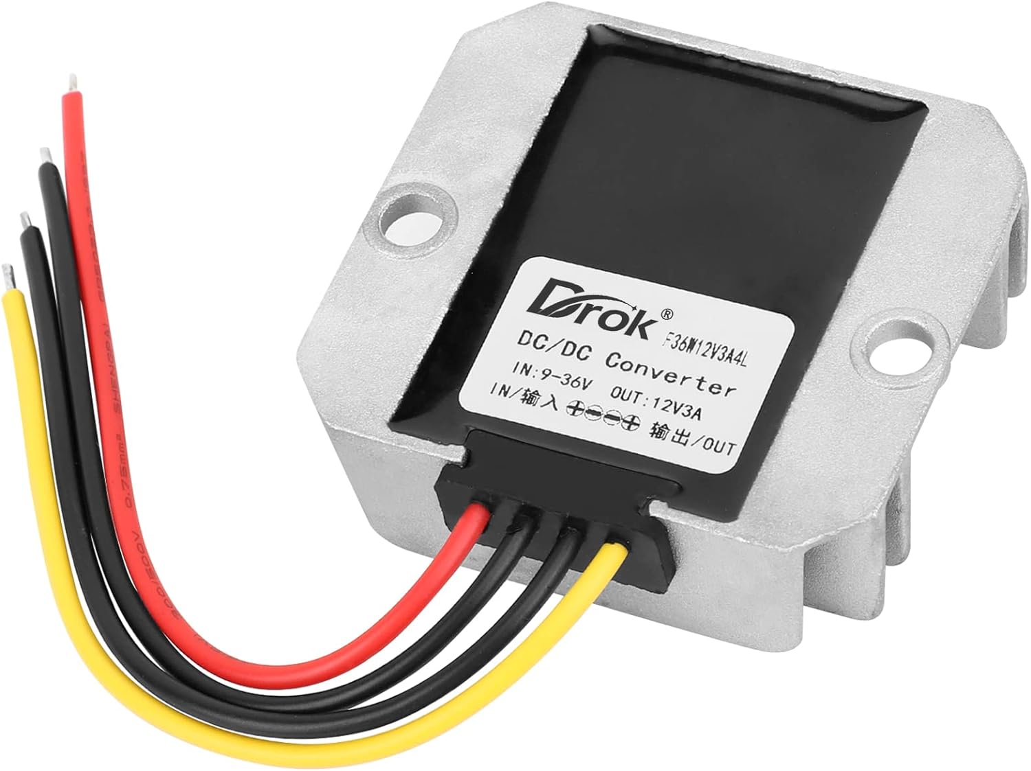 Best at this point, is to add voltage regulation. A 12VDC buck-boost converter has been a very good addition. This prevents the ion injection from varying greatly as engine voltage varies from 11 to 15 volts, as it often will. This one by Drok has been working very well, though it’s overkill for power capacity, the quad units take very tiny amounts of current, less than 0.1 amp each.

- The next step, and this is essential to go any further, is temperature control. We must not inject too much ionized air in the cold, or we will start to lose spark plugs. This unit, available from many different vendors, is the current best turnkey recommend we know. So far it has been just great to shut off below 35F (1.67C), with the sensor placed inside the air filter compartment. We have found that air in the compartment can vary to much lower than outside, until the engine is heated up. The only downside to this component, is that the LED readout may degrade over a year’s time in the heat-and-cold of an engine compartment. Right now I am running using a very nice Arduino-based unit built for me by a good friend; more on this in the future!
- At this point we can ramp things up in a number of different ways. One clip seems to send a lot, so I have left engine-idle at one clip (though full 12VDC now, for a while I ran it at 5VDC, but not after I set temperature control to 35F/1.67C), and put in an RPM switch to control a Stage II.
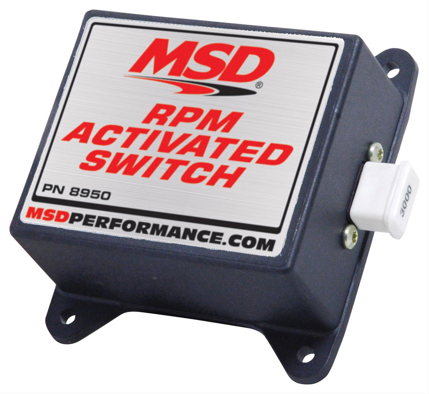
Nothing runs at less than 35F/1.67C inside the air filter compartment; Stage I runs when the temperature switch says go; Stage II starts up when the engine is just higher than high-idle, which on this V8 is about 1100 RPM. The RPM switch itself turned out to be a problem taking almost two years to resolve: two different mass-market RPM switches, both widely available from many major web vendors, did not work properly on the Tahoe, and support said it was RF interference which they could not advise about. Eventually I was able to afford the widely-recommended MSD 8950, with the 8677 adjustable RPM module, and this has worked very well.